fsteeg.com
| notes
![]() | tags
| tags
∞ /notes/arduino-eclipse-and-the-joy-of-extending-your-ide-into-the-physical-world | 2010-01-25 | eclipse programming tinkering
Arduino, Eclipse, and the joy of extending your IDE into the physical world
Cross-posted to: https://fsteeg.wordpress.com/2010/01/25/arduino-eclipse-and-the-joy-of-extending-your-ide-into-the-physical-world/
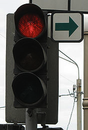
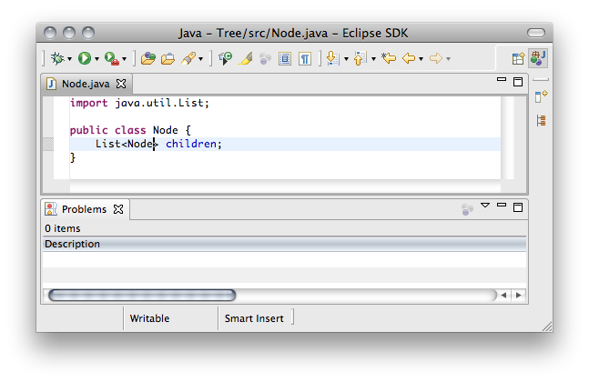
Ever since I read about using Java and Lava to monitor project build status in Mike Clark's Pragmatic Project Automation, I was thrilled by the idea of extending your IDE into the physical world. When I recently listened to an episode of the Chaosradio Express podcast about tinkering in the 21st century (in german) and learned about Arduino, I thought this could be simple enough for me to get started with electronics and so I ordered a Fritzing Starter Kit and a book on Getting Started with Arduino. With red, yellow and green LEDs included in the set, I had the idea of building something like a coder's traffic light. The Eclipse problems view seemed like a good place to start as it contains content for red (errors), yellow (warnings) and green (empty view) state. Also, it is very configurable about what's showing (through Mylyn or Configure Contents) and could thus be used flexibly with a very simple approach. So this is the basic idea: If we are completely off while coding, and we're writing something likeList<>, we get the stop signal from Eclipse:
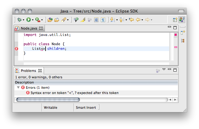 Now we try to do a little better, removing these confusing pointy brackets and write just
 List, which is better, but not quite right yet, and Eclipse tells us so:

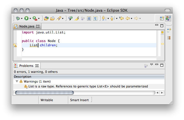 Now we remember it should be a
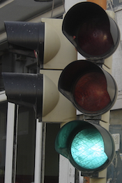
 List<Node>, and with an empty problems view we are good to go:
 In addition to the basic functionality of red, green and yellow lights, it would be cool if these lights would not be blindingly bright all the time, but rather adjust their brightness according to ambient light when coding in dim settings. Also, we want to turn the device on and off and have a separate light indicating if it's on or off.
The first step to make the thing real is to build the hardware prototype using an Arduino, a solderless breadboard, LEDs, some wires and resistors, two buttons and a light sensor (image created with Fritzing):
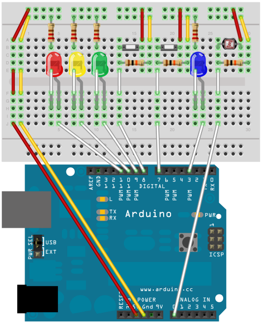 Now that we have the hardware set up, let's write the code for the Arduino. This is the code we upload to the Arduino hardware from the Arduino IDE. First we define shortcuts for the pins used, set the pin modes, and open a serial connection from the Arduino to the computer:
void setup() {
  pinMode(BLUE, OUTPUT);   // #define BLUE 3
  pinMode(GREEN, OUTPUT);  // #define GREEN 9
  pinMode(YELLOW, OUTPUT); // #define YELLOW 10
  pinMode(RED, OUTPUT);    // #define RED 11
  pinMode(ON, INPUT);      // #define ON 8
  pinMode(OFF, INPUT);     // #define OFF 7
  Serial.begin(9600);
}boolean on = false;
void loop() {
if(digitalRead(ON) == HIGH) on = true;
if(digitalRead(OFF) == HIGH) on = false;
if(on) turnOnLights(); else turnOffLights();
}void turnOffLights() {
digitalWrite(GREEN, LOW);
digitalWrite(RED, LOW);
digitalWrite(YELLOW, LOW);
digitalWrite(BLUE, LOW);
}void turnOnLights() {
turnOffLights(); dim(BLUE, 5, 25);
switch(Serial.read()) {
case 0 : dim(GREEN, 25, 255); break;
case 1 : dim(YELLOW, 25, 255); break;
case 2 : dim(RED, 25, 255); break;
default: turnOffLights();
}
Serial.flush(); delay(1000);
}void dim(int output, int mini, int maxi) {
analogWrite(output, map(analogRead(0), 0, 1023, mini, maxi));
}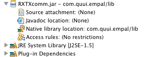 I had to rename the native library to
 RXTXcomm.jnilib to make this work. Also, RXTX only works with Java 5, so on my Mac I had to get Java 5 from Leopard to make this work on Snow Leopard. As Java 5 from Leopard is 32 bit, I had to use a 32 bit version of Eclipse, too. I also had to create a writable directory /var/lock. With the library set up, we can now connect to the Arduino from within the Java code in our Eclipse bundle. We first set up the connection, specifying the cu.usbserial port that is set up in the Arduino IDE:
String portId = "/dev/cu.usbserial-A9007WtK"; // from Arduino IDE
CommPortIdentifier id = CommPortIdentifier.getPortIdentifier(portId);
SerialPort port = (SerialPort) id.open("Eclipse-Arduino", 1000);
final OutputStream output = port.getOutputStream()Runnable that gets the status from the problems view and sends the current state through the serial USB connection to the Arduino (note that this is not particularly clean as it uses internal API and relies on the specific format of the description string, but it's short and illustrates how to interface with the Arduino hardware from an Eclipse bundle):
final Runnable sendStatus = new Runnable() {
  public void run() {
    String viewId = "org.eclipse.ui.views.ProblemView";
    IViewPart view = getSite().getPage().findView(viewId);
    if (view == null) return;
    ProblemsView problemsView = ((ProblemsView) view);
    String desc = problemsView.getContentDescription();
    try {
      int err = 2, warn = 1, ok = 0;
      output.write(
                desc.contains("0 items") ? ok
              : desc.contains("0 errors") ? warn
              : desc.trim().length() > 0 ? err : -1);
    } catch (IOException e) { e.printStackTrace(); }
  }
};Runnable asynchronously in a background thread:
new Thread(new Runnable() {
  public void run() {
    while (true) {
      parent.getDisplay().asyncExec(sendStatus);
      try {
        Thread.sleep(1000);
      } catch (InterruptedException e) { e.printStackTrace(); }
    }
  }
}).start();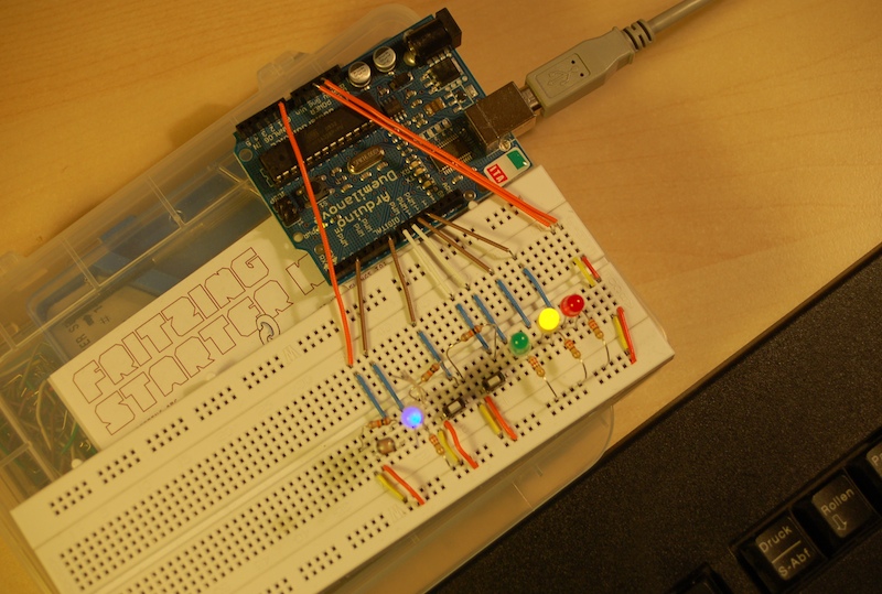 And it doesn't have to stop here: how about moving those lights into the keyboard, or building a Lego case for it, or even creating a real circuit board and custom case for the device. And on the software side, we could make it configurable for different Eclipse views (like the JUnit view) or connect it to continuous integration. Tinkering on hardware and software tooling with Arduino and Eclipse - oh joy!